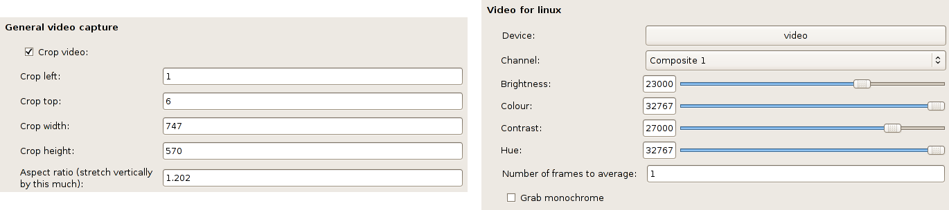
Figure 3.1: Recommended video preference settings
Most museums use tube cameras (usually called Vidicons) for infrared imaging. Although they are relatively cheap they are not very stable and they suffer from (sometimes quite severe) geometric distortions. More modern solid-state cameras are still expensive but are becoming more widely used because of their greater stability. This guide assumes you are using a tube camera but almost all of it applies to solid-state cameras as well.
Whatever your camera there are three main sources of error which have to be addressed in order to be able to make successful mosaics:
The first two problems will be different in each Vidicon and will change each time a tube is replaced. All three problems need to be addressed to create successful infrared reflectogram mosaics.
It is vital that the optical axis of the Vidicon is at right-angles to the picture plane and that, whether it is the Vidicon or the painting that moves during image capture, it remains perpendicular. Obviously, with a seriously warped panel, this may not be possible. The lighting should be carefully adjusted so that the area of interest is lit as evenly as possible. If you can, arrange for the lights to remain stationary with respect to the camera.
An easy way to test camera alignment is to image a piece of graph paper, move the camera (either left-right or up-down) by 90% of the field of view, and see how features in the overlap area move. First rotate the centre around the optical axis to get the centre line of the images lined up. Next check the corners and adjust camera pitch and yaw.
On Linux, you can capture video directly into nip2 provided that your capture card is compatible with v4l. You may need to adjust the nip2 video settings. These settings can be found under the headings Video for linux and General video capture in the Preferences window, which can be accessed by selecting Edit / Preferences from the main nip2 window. The default settings, see Figure 3.1, are for the Hauppauge PCI capture card and should be changed as required.
Once you have set up your card, select Tasks / Capture / Capture Video Frame to create a new video object, which will appear as a still image in your current selected column. The captured image can be updated by opening the image in a viewing window and then pressing Ctrl-C (a shortcut for File / Recalculate Image).
You can create more than one video object: this can help you to get the overlaps right if you have two open at once (one showing the previous grab) when you are moving the camera around.
While it is possible to correct geometric distortions after the image is captured, it is difficult to do the necessary modelling accurately and reliably. Instead, we suggest the grabbed images should simply be cropped, since the most severe distortion affects the perimeter of each video image.
To determine the area to crop, set up the Vidicon as it would be set to image a painting and capture an image of a rectangular grid — a piece of graph paper works well as a target. Before capturing the grid, check the current video crop settings in the Preferences window and ensure that the crop is set at maximum: left 0, top 0, width 768, height 576 (these are the dimensions for a PAL signal, they may be different on your system). Also set the Aspect ratio line to 1.
Create a new video object and look for the largest rectangle with little distortion (no more than a few pixels). If you create a region on the video image (by holding down the Ctrl key and dragging down and right with the left mouse button, see §??) you can compare the straight edges of the region against the distorted lines of the grid. You can then expand and contract the region until you decide on the optimum area. The settings you need for the crop box can be taken from the values contained within the region object, which can be viewed by left-clicking several times on the down arrow to the left of the region object name.
Finally, you can set an aspect ratio: nip2 will automatically stretch video frames vertically by this factor. You can measure the aspect ratio of your capture card by taking a picture of something you know to be square and dividing the width in pixels by the height in pixels.
Move back to the Preferences window and enter the crop values in the General video capture section. Next time you create a new video object, you should find that it is cropped to the appropriate area. The settings you enter in the Preferences / window will be saved and automatically loaded again next time you start nip2. See appendix A.
Choosing the usable area of the image is a matter of compromise — the smaller the area, the more images are required to build a mosaic of a particular painting. If the area chosen is too large then the amount of distortion can cause serious errors in the final mosaic.
It’s possible to use the VIPS rubber sheet plug in to detect and correct geometric distortion in your images automatically. This lets you use the full area of the sensor. It is a bit fiddly, but see the rubber sheet documentation if you are determined.
Once everything is correctly set up, position the painting in front of the camera and experiment with the gain and offset settings on the Vidicon to achieve the optimum infrared image on the computer screen. Note that the appearance of the image on the computer will normally be different to its appearance on the video monitor connected directly to the camera.
Repeat this process at different points across the whole area to be captured. Although it is not always possible, the aim is to find a setting that does not need altering much during the capture of the data. This seems to lead to more successful mosaics.
To counteract the problem of uneven sensitivity across the target area of the tube, it is necessary to capture an image of a piece of grey card. This grey card image is then used to correct all subsequent images. The card should be a flat, even grey, of around 50% reflectance. The Vidicon and lighting positions with respect to the painting should not be changed between the imaging of the grey card and the capturing of the mosaic. A grey card can be captured at any time, but it is good practice to start with one — you may forget later.
If your mosaic will take several hours to capture, you may wish to grab extra grey cards, since the sensitivity of the tube can change as it warms up. Be sure to note which data images correspond to which grey cards!
In association with the first grey card, it is a good idea to grab an image of your grid to record the scale at which the data images are being made.
Open a video window, Tasks / Capture / Capture Video Frame, and when it shows the desired area, save the file. The choice of file name is a question of personal preference. We find it helpful to use a format that indicates where in the mosaic the data comes from — for example, dat3.5.v for the fifth image in row three.
It is helpful to be able to see the previous image to ensure that there is sufficient overlap. To achieve this, a second video window can be opened and placed alongside and the images grabbed into alternate windows.
Before the mosaic can be assembled, the data images need to be corrected for non-uniformity of illumination using the grey card image. This function can be performed within nip2 or directly using a predefined VIPS command-line tool.
First, close nip2 and open a command line window, (xterm, mingw, etc). Move to the directory containing your image files with cd. For example, if you have made a directory called raphael inside your home directory, type:
The program you need to use is called light_correct. You need to give it the name of the grey-card image and the names of all of the image files you want it to correct with that gray card. Suppose you have saved your gray card image as grey.v, and your painting image files are called dat1.1.v and dat1.2.v. You would then enter:
The program will run and print messages explaining its progress. It creates a new set of corrected image files, with the same names as before, but prefixed with ic_. In this example, it would create two new images files called ic_dat1.1.v and ic_dat1.2.v.
If there are a lot of image files to correct this could mean a lot of typing. Fortunately, you can use wildcard characters to abbreviate lists of file names. The example above can be abbreviated to:
The dat*.v means ‘any filename which starts dat and ends with .v’.
You can use this technique to correct different parts of your mosaic with different grey cards. If you have a file called grey1.v for the first row in your mosaic, and a file called grey2.v for the second, you could do the correction in two parts:
The function within nip2 used to preform this correction is Tasks / Capture / Flatfield. A set of images can be corrected at the same time by joining them together in a Group. A group can be produced by selecting all of the required images and then using the Edit / Group command.
Load all of your images into nip2, and group all the image except the grey image. Select your grey image and then your new group and then run the Tasks / Capture / Flatfield function. This will produce you a group of corrected images. Right-click on this new group and select Save As from the menu. In the save window type in a name, for example fred_01.v and then hit the save button. All of the images in your group will then be saved as fred_01.v, fred_02.v, fred_03.v … fred_n.v.
If you want to keep row numbers in your file names, (see §3.1.2), you will need to correct your images one row at a time, saving each row as fred01_01.v, fred02_01.v, etc.